By CPM Pipelines team
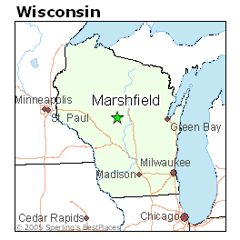
The City of Marshfield, Wisconsin has actively maintained the local environment for over 140 years. Located in central Wisconsin, Marshfield has provided wastewater collection and treatment services since 1880 and currently serves a population of 19,478 residents.
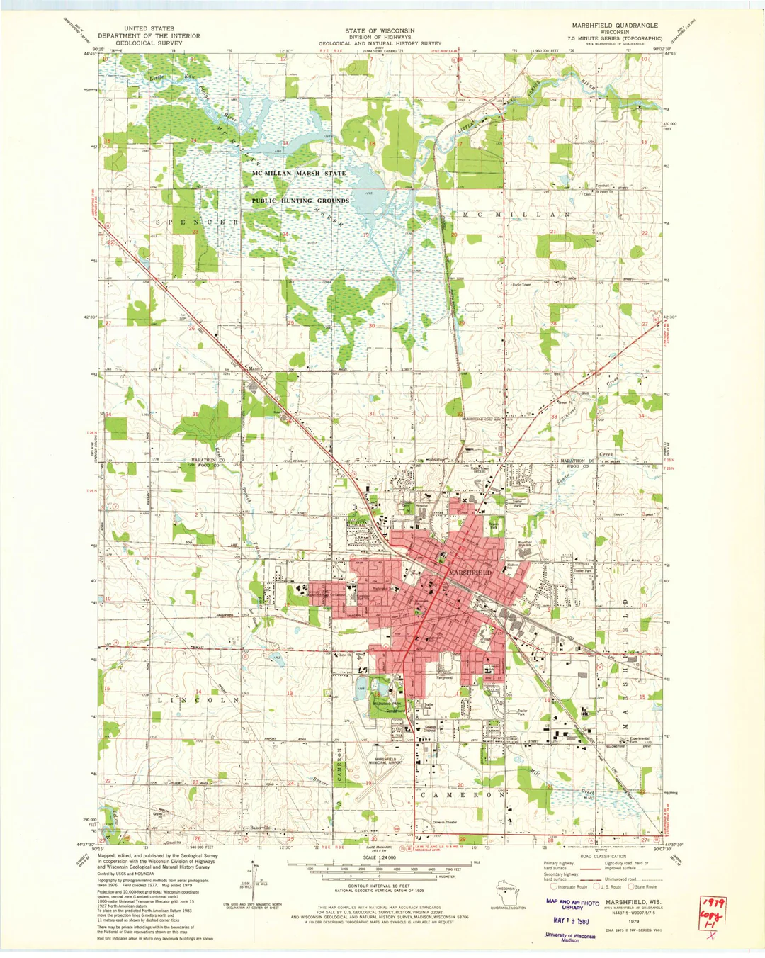
There are over 138 miles of sanitary sewer lines in the city that convey wastewater to the treatment plant. This system includes approximately 2,500 manholes spaced at 200–600 ft intervals to facilitate inspection, cleaning, maintenance, and sampling. Wastewater that cannot flow by gravity to the treatment plant is pumped from four lift stations located on the north and west sides of the city. Pumps at these stations convey flow through forcemains to higher elevations, where gravity flow resumes.
One major concern in the proper operation of the collection system, and ultimately the wastewater treatment facility itself, is infiltration of clearwater (rain, snow melt, and groundwater) into the system. This clearwater causes excessive flows and hydraulic stress at the wastewater treatment facility and within the collection system. In the worst cases, infiltration can exceed the gravity pipe’s capacity and cause sanitary sewer overflows. Most wastewater utilities have active gravity sewer inspection, maintenance and rehabilitation programs to minimize infiltration sources. A portion of the wastewater collection system often left unchecked is the condition of forcemains. A forcemain can incur damage from corrosion, erosion, hydrogen sulfide attack, excavating and directional drilling. A breach of a forcemain will cause an immediate exfiltration of wastewater and likely a Sanitary Sewer Overflow.
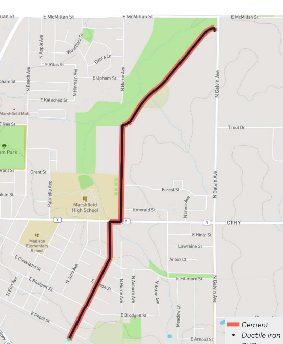
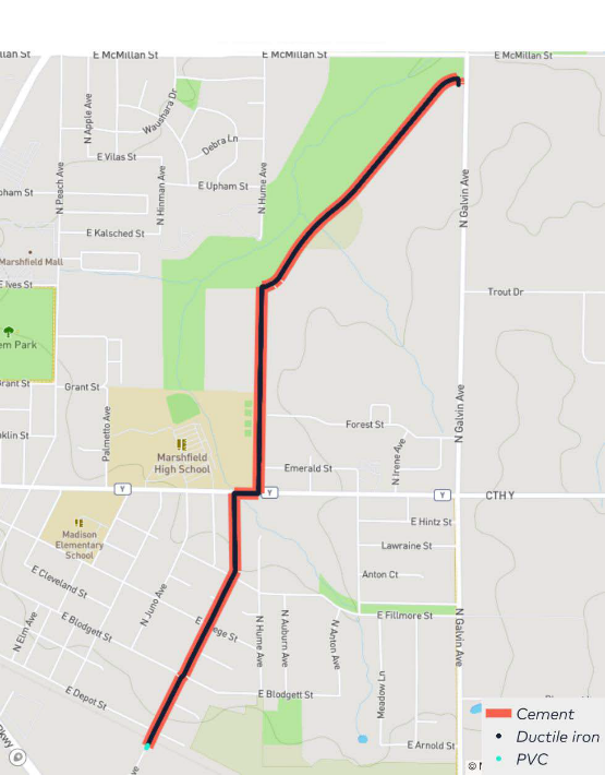
On November 8, 2023, staff in Marshfield noticed the wastewater treatment plant was receiving approximately 1 mgd less flow than normal. This discrepancy was traced to a leak occurring from the Northeast Lift Station’s forcemain. This forcemain is a 20 inch diameter cement lined ductile iron pipe that runs 2 miles in length. The leak occurred under a street and was discharging to the surface from a severely rusted, corrugated metal stormwater culvert. The location was obvious when the upstream side of the culvert was compared to the downstream side. The creek on the upstream side had a minimal flow of clear water while the downstream side had an increased flow of tainted water.
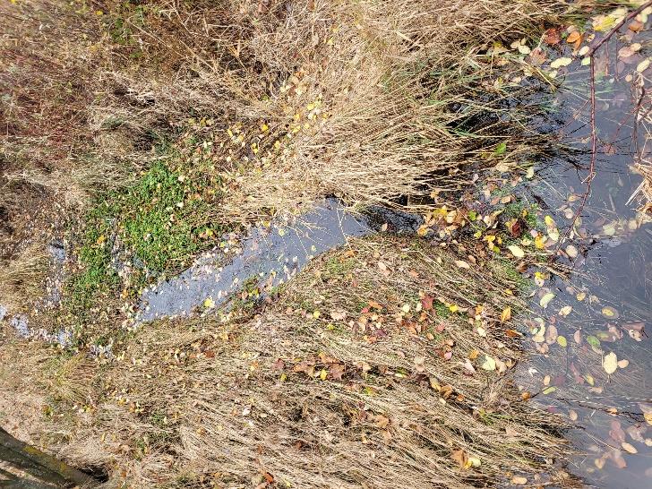
Upstream Side of Culvert
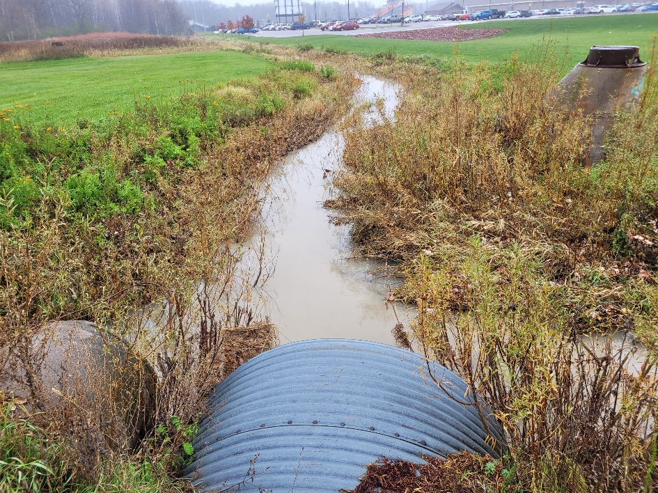
Downstream Side of Culvert
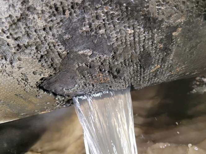
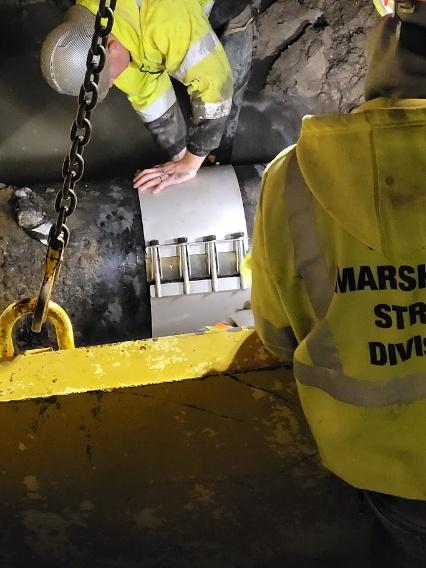
When the pipe was excavated the cause of the exfiltration leak was evident. A 4-inch hole had formed due to severe exterior corrosion at this portion of pipe. Although the exact cause of the corrosion is unknown, it was likely influenced by acidic soils or chloride contamination from winter road de-icing. Notably, the first mile of the forcemain—passing through undeveloped land—showed fewer defects than the second mile located in a developed residential area. The damaged section was repaired using an external repair coupling.
This incident made it clear that a full evaluation of the forcemain was necessary. Key questions included whether this corrosion was an isolated defect, one of several localized problems, or indicative of widespread deterioration along the entire two-mile length. At the time of the SSO, a lift station upgrade project was already in the design phase, so forcemain evaluation methods were added to the engineering firm’s scope of work. All feasible inspection methods required inserting a Pipe Inspection Gauge (PIG) device inside the forcemain. Because the lift station lacked the necessary infrastructure to launch such a device, a launch vault and associated piping were incorporated into the upgrade design.
The engineering firm identified four contractors capable of performing in-pipe forcemain inspections. Three expressed interest in providing services. After interviews with city staff and the engineering firm, CPM Pipelines was selected and used the Acquaint Acquarius™ inspection tool to assess the condition of the forcemain.
In August 2025 the inspection was carried out by CPM Pipelines utilizing the Acquarius™ NDT inspection technology. The inspected pipeline is a 20″ Ductile Iron pipeline with cement lining and some PVC sections at the end of the alignment where it outfalls to a gravity manhole. The main objective of the inspection was to gain insight into the overall condition of the pipeline and identify potential failure mechanisms. Additionally, the materials used and the pipeline’s location are mapped out. The NDT tool is an intelligent Pipeline Inspection Gauge (PIG) and has been developed together with various wastewater utilities and drinking water companies. The tool measures various properties of the pipeline. It utilizes, among other things, ultrasonic sensors and advanced inertial measurement unit sensors (IMU). The analysis revealed several findings including measured wall thickness, pipeline deviation from the provided trajectory, angular displacements at joints, joint gap widths, delamination, sulfate attack, cement lining deterioration and other anomalies. Damage to the cement liner has been observed along nearly the entire pipeline length. In addition, numerous locations exhibiting delamination and external wall damage were detected.
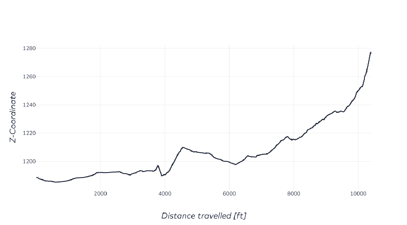
The inspection revealed a number of critical and important issues with the pipeline. From a location perspective, none of the pipe sections were found to be more than 6 feet from the location identified on the as-built drawings and the city’s GIS. Having an accurate location of the pipeline will assist the city in the future when additional work is required on this forcemain. The depth profile indicates a gradual upward slope of the pipeline. This is important because it indicates that there will be few gas pockets and limited internal defects due to hydrogen sulfide buildup.
The next parameter measured was angular displacement or joint deflection. Joint displacements greater than 4 degrees for PVC pipe and 5 degrees for DI pipe are deemed to be extreme. These are calculated based on the IMU sensor on board the inspection tool. A total number of nine joints exceed the thresholds of the materials. These include six joints that exceed the thresholds in the horizontal plane and three that exceed the threshold in the vertical plane. It is possible that these connections are deliberately installed with excessive angular displacement to make a curve over multiple pipe sections. Next, the issue of gap widths was analyzed. Gap widths in excess of 1.4 inches is deemed to be excessive. A total of two joints with extreme gaps were identified within the DI pipeline. For both joints, the type of connection used is unknown so it is important to assess whether the joint gaps indeed exceed the critical limits. Continued monitoring of these joint gaps is advised to track any potential worsening over time.
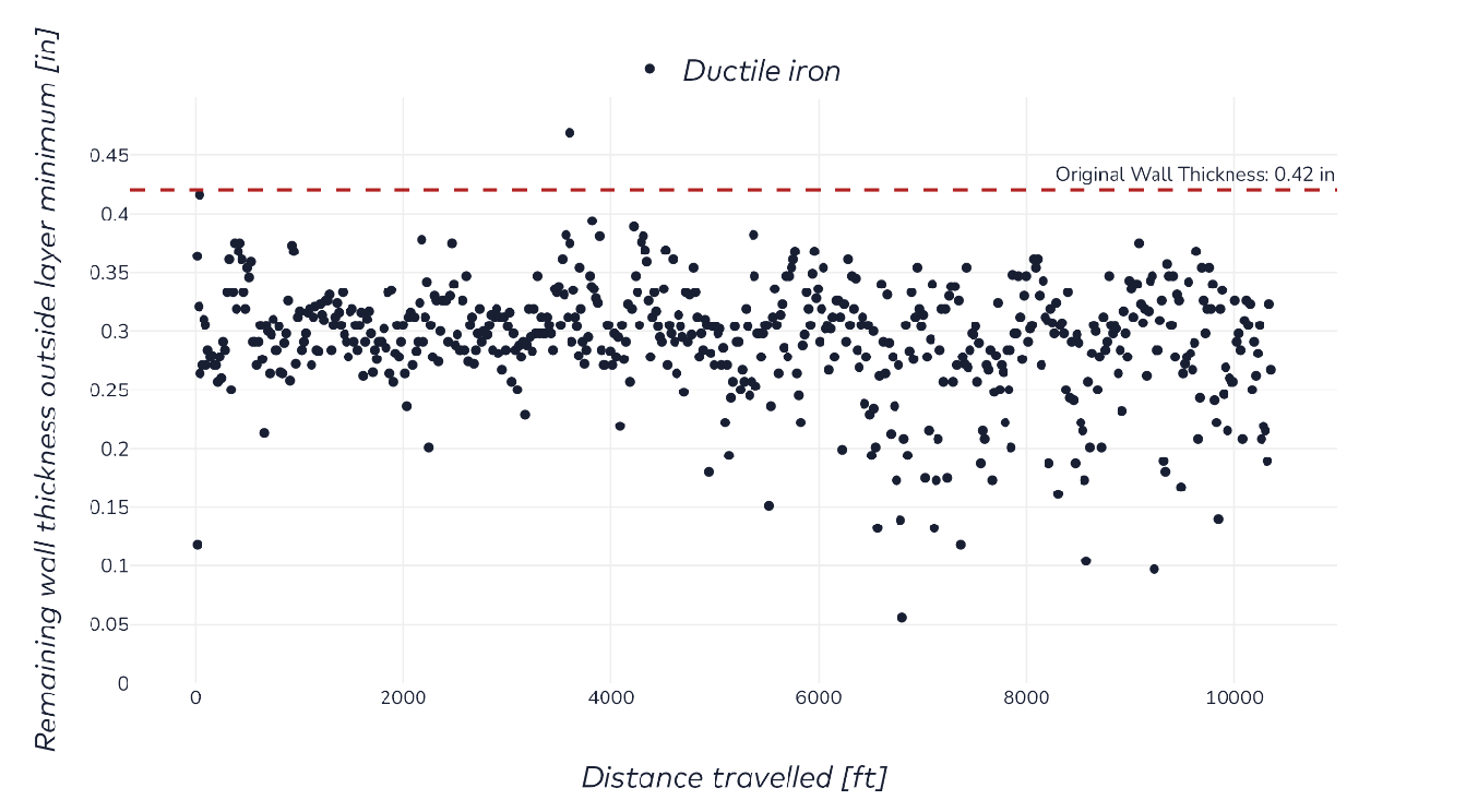
One of the most important condition assessment parameters that the inspection device analyzed is wall thickness. Both for the cement lining inner layer and the ductile iron outer layer. With the UT data, it is possible to determine the wall thickness of the pipe materials in the inspected section based on thousands of measurement samples. These large number of measurements determine both the average remaining wall thickness and the minimum remaining wall thickness per pipe section. The wall thickness is based on the speed of sound for the used materials in the trajectory. This allows the wall thickness to be determined for every pipe segment. The ductile iron pipeline was assumed to be AWWA Class 52 based on the information given by the client prior to the start of the inspection. This corresponds to an original ductile iron thickness of 0.42 inch. Furthermore, the pipeline has an internal cement liner with original wall thickness 3/32 inch. For both the ductile iron and cement liner the wall thickness could be analyzed due to the variation in thickness of each material type. The wall thickness of the cement liner and the ductile iron together form the wall thickness of the entire wall. Following the analysis, it has been determined that the average remaining wall thickness for the majority of the ductile Iron pipe segments (iron + lining) falls within the range of 0.52 to 0.60 inches. The PVC pipe segments at the end of the trajectory have an average wall thickness of 1.18 inches. The 20” PVC pipe segments with a wall thickness of around 1.2 inches correspond to the DR18 pressure class 235 psi.
The minimum wall thickness detailed in the graphic below show that a significant number of the pipe segments in the second half of the pipeline contain localized regions where a significant amount of the wall has deteriorated. In all of these cases this is caused by significant corrosion on the outside of the pipe.
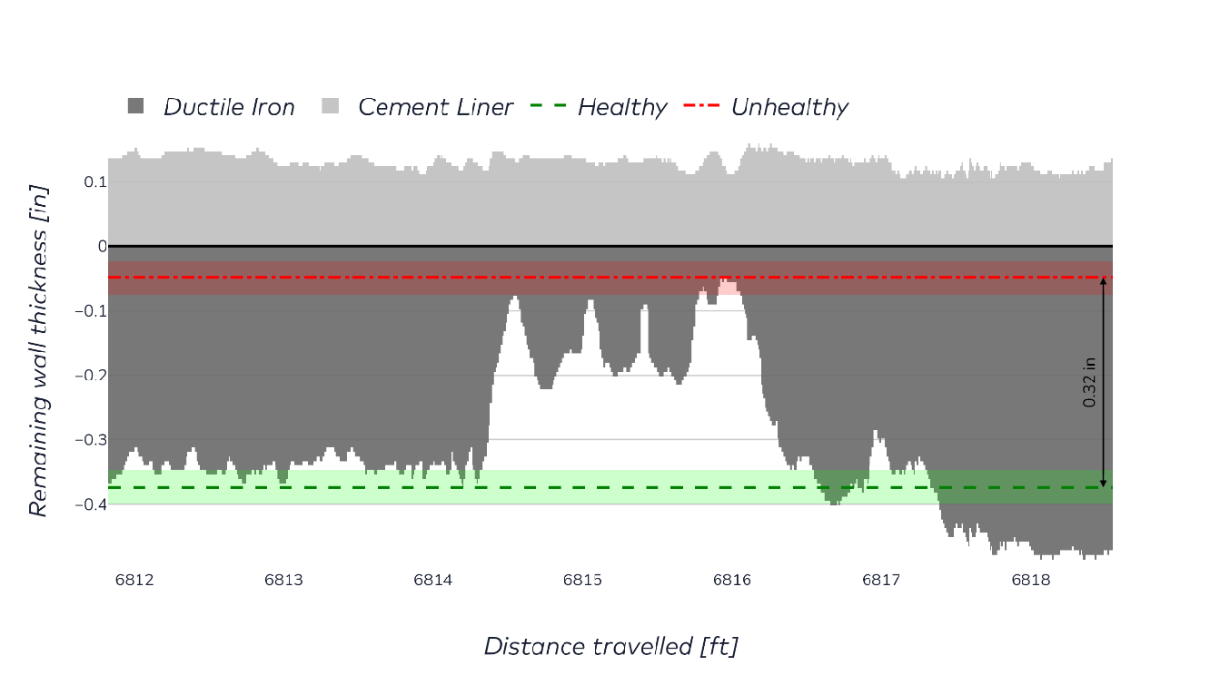
To illustrate the condition of the pipe in these impacted segments the figure below shows that the reduction in pipe thickness is primarily due to corrosion from the outside of the ductile iron pipe. The cement liner is intact and healthy in this location. The ductile iron has significant lengths where corrosion has seriously impacted the integrity of the pipe.
In pipelines consisting of multiple layers, delamination might occur. With delamination, the cohesion between the different layers reduces, resulting in the layers separating from each other. A total of 4,361 instances of delamination were identified where the cement liner is separating from the DI pipe. Leakages are detected using a hydrophone. The results show that there was no noticeable increase in the sound signal in this pipeline. This indicates that no leakages have been detected in the inspected pipeline by means of the hydrophone. Sulfate attack (H2SO4) can occur in the concrete and asbestos cement pipe segments of wastewater pipes and can cause the pipe to deteriorate into a critical condition. At only one location along the inspected pipeline, H₂SO4 attack was observed. The attack is in an early stage; the material is still present, but the integrity of the cement is beginning to deteriorate.
Due to several causes, such as corrosion of the material layer, sulfate attack or erosion of the cement, deterioration in cement liners can occur. Along nearly the entire pipeline alignment, a suspected defect in the cement liner was observed at the invert (6 o’clock position) and may be caused by calcium leaching from the cement matrix. The resulting loss of calcium weakens the cement. Or, it may be due to erosion from settled grit or rolling sediment in the conveyed sewage causing deterioration at the invert location.
This is one of a number of projects analyzing sewer forcemains that have been undertaken over the last few years in the United States using this NDT technology. The defect results identified in this study were similar to the other efforts. In addition, there are some universal observations that can be made over and above the defect analysis that can provide valuable insights to utility and pipeline operators and managers.
The NDT identifies exact location of the pipeline underground in a three-dimensional manner. This knowledge is critical. As-builts are relied upon when planning, designing and conducting underground construction projects. They are not always accurate. Having exact locations of underground infrastructure alleviates uncertainty in planning and design and cost extras due to unforeseen circumstances.
The tool is able to identify previous repairs and note them as anomalies. By overlapping anomaly detection with known repairs, the veracity of the analysis can be confirmed. This adds certainty to the decisions made based on test results.
Another value of the data is that surface activities can be correlated with subsurface pipe defects. The use of salt for ice removal on roadways was correlated with increased corrosion of the metal pipeline in areas where it ran under streets, and not where it ran over land. This information allows the utility to make operational decisions and understand the impacts of those decisions on all underground infrastructure, not just the pipeline being inspected.
The data collected by the tool identifies defects and anomalies with high locational precision. This means a utility can determine which stick of pipe is most negatively impacted. It also provides information on where the pipe segment is most impacted. The results show that defects and impacts are not evenly distributed throughout the pipeline, but are clustered. This assists the utility in planning rehabilitation or replacement capital programs in a more targeted manner with a less costly result. Targeted pipe lining or cathodic protection installation can be used to minimize cost, surface impacts and maximize pipeline life.
Performing the NDT inspection over time can provide valuable insights into the overall health profile of the pipe and the trends it is experiencing. It can also inform the operator about the impact of improvements made so that the asset management program can be refined.
The NDT program provides more than just defect identification information. It provides operational insight which in turn provides the utility with actionable knowledge to make the best decisions from a cost effectiveness, asset life and reliability perspective.
About CPM Pipelines
CPM Pipelines is a U.S.-based infra-structure services company specializing in pressure pipe condition assessment and trenchless rehabilitation solutions. The company supports municipal, industrial, and utility clients by delivering advanced inspection technologies and innovative re-pair systems that extend pipeline life and improve long-term asset performance.